One of the most vital facets of precast concrete construction is connecting the various precast concrete members to each other, to foundations, and to other types of construction, such as structural steel, masonry (CMU), cast-in-place concrete (CIP), wood, etc., that are part of the project structure. Individual connections and connection systems are crucial and play an important role in completing a sound and well-functioning structure. A connection system consists of strategically located and sized connections between building components that determine how forces are transmitted throughout the structure and eventually to the foundations. The connection system determines the overall behavior and structural stability of the precast structure.
Connection Considerations
Connections usually consist of three separate parts. Using a welded connection that attaches two members together as an example, the connection would consist of embedded steel plates in each of the two members and a connecting steel plate (often called a loose plate or strap plate) that is welded to each of the embedded plates. The embedded plates are anchored to the concrete by the use of headed steel studs or reinforcing bars welded to the plate. Once erected, the embedded plates on each member must properly align both vertically and horizontally so that the strap plate can be located with sufficient fit or overlap for the weld to be completed.
In order for a successful connection to be made, the drawings, member fabrication, and field fit-up between the pieces must all be correctly done. This is quite a challenge for all parties involved. Tindall has a talented staff of engineers and detailers who can assist the project engineers and detailers to develop feasible solutions concerning all aspects of precast connections.
Life Cycle of a Connection, Associated Loads, and Connection System
How does an individual connection and a connection system come about? This section explains the development process of a connection and the entire connection system.
It starts with the overall analysis of the structure. This involves determining how the structure will behave or respond to the forces applied to it. These forces are many and varied, but can generally be thought of as vertical, lateral, and volume change forces. The Tindall engineers must first identify the Codes that are applicable and to be used in the analysis of the structure.
These Codes define the live loads, or occupancy loads, to be vertically applied to the horizontal members, such as flat slabs, T-Slabs, and double tees. Additionally, the Codes specify the level of seismic excitation and wind speeds and resulting wind pressures. Other loads, like the horizontal pressure of retained soil, are also determined based on the project site conditions. All of these forces are considered external forces.
Another type of force that must be considered is that of volume changes to the precast members and the completed structure. These are internal forces. Volume change forces result from the shrinkage and creep of the members. Precast members are made of concrete. Concrete shrinks or shortens as time goes by, and the concrete continues to lose moisture from the time it was first made. For example, a 50-foot-long member may shorten by as much as ¼” or ⅜”. If this shortening isn’t restrained by some way of holding the ends from moving, then there are no external forces generated. However, if end connections are rigidly attached to other members, then restraint forces result. These forces can be significant and can cause pullout of embedded plates or breaking of welds. This same concept applies to concrete creep. Creep is a term used to identify potential shortening of concrete members subjected to a sustained force. In prestressed members, this sustained force is due to the compressive effect of any prestressing used in the member. When members are restrained against creep, the resulting forces are similar to those of concrete shrinkage. Another type of volume change force is due to temperature fluctuations. Like most materials, concrete expands as the temperature rises and contracts as the temperature drops. As with creep and shrinkage, if members are restrained against temperature-induced expansion or contraction, the resulting forces may be significant.
The connection concept is driven by the Tindall Specialty Engineer. The engineer is the one who must first analyze the external forces on the structure and then define a load path for the forces to travel around the structure, member to member, and then find their way to the foundation. For example, seismic excitation occurs in the soil supporting the structure. As the soil moves, the inertia from the soil movement causes a relative displacement between the soil and the structure, i.e., the structure sways. This swaying causes forces within the structure, which must then be transferred through the connection system back down to the foundations, which are supported by the soil. This is typically accomplished by connecting the floor members together to create what is called a diaphragm. This horizontal diaphragm then transfers forces to vertical members, such as wall panels that act as shear walls, which transmit the forces down to the foundation. Each of these load transfers or “handoffs” must be accomplished by connections.
The Tindall engineer is the driving force behind all aspects of the connections, determining the connection forces, developing the connection concept, design of embedments, welds, details on drawings, as well as fabrication and field constructability.
Connection Types Explained
Connection types can be categorized as follows:
- Bearing type – an example of these would be a beam sitting on a bearing pad supported by a column corbel, or a double tee stem on a bearing pad supported by a corbel or ledge.
- Dry Connections – these connections are welded or bolted connections
- Wet Connections – these are connections that use field-placed concrete or grout, such as splice sleeve type connections
- Proprietary Connection devices and systems manufactured by companies involved in supporting the precast industry
Bearing Connections
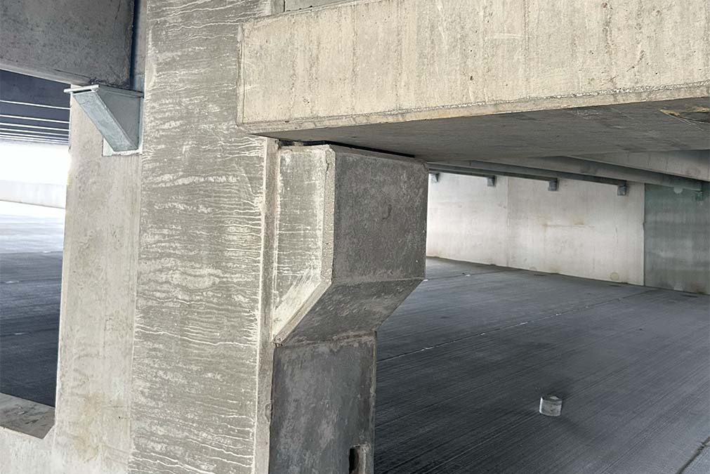
Bearing connections are used wherever a horizontal member must be supported by a vertical member or another horizontal member. Typical horizontal members are floor slabs, double tees, and beams. An example of one horizontal member supporting another horizontal member is when a double tee stem is supported on a bearing pad on top of a beam ledge. This beam is then supported by a vertical member, such as a wall or column. Figure 1 is a photo of a couple of bearing conditions. The physical makeup of a bearing pad consists of randomly oriented synthetic fibers impregnated in an elastomer compound. This combination creates a pad that is durable and that can deform. The ability to deform helps to mitigate potential restraint forces from volume changes in the precast members and structure. There are no positive attachments between the bearing pieces making up the bearing assembly. For example, no glue or anything like that is used. The bearing components rely on friction only.
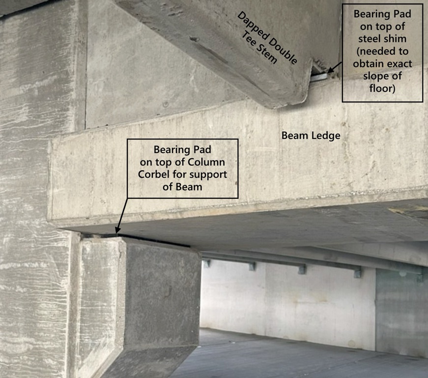
If the double tee bearing is closely examined, it can be seen that a steel shim plate has been placed under the bearing pad and on top of the beam ledge. Shims such as these are sometimes used to fine-tune the alignment of the top surfaces. This is particularly common for double tees used on a sloped area, as with a ramp in a parking structure.
Dry Connections
Dry connections are called dry simply because nothing “wet” is used to make the connection. These are common to conditions such as connecting one double tee to another, a double tee to a beam or spandrel, a beam to a column, or a wall panel to a foundation.
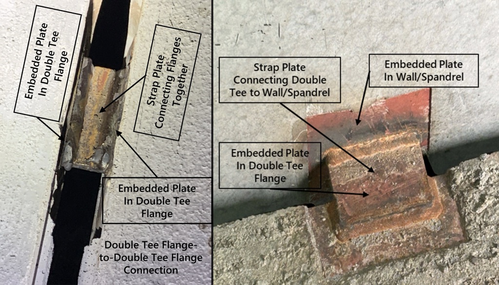
There are two main subcategories of dry connections – welded and bolted. By far the majority of dry connections used in precast construction are welded connections. Figure 2 is a photo of two types of typical welded connections.
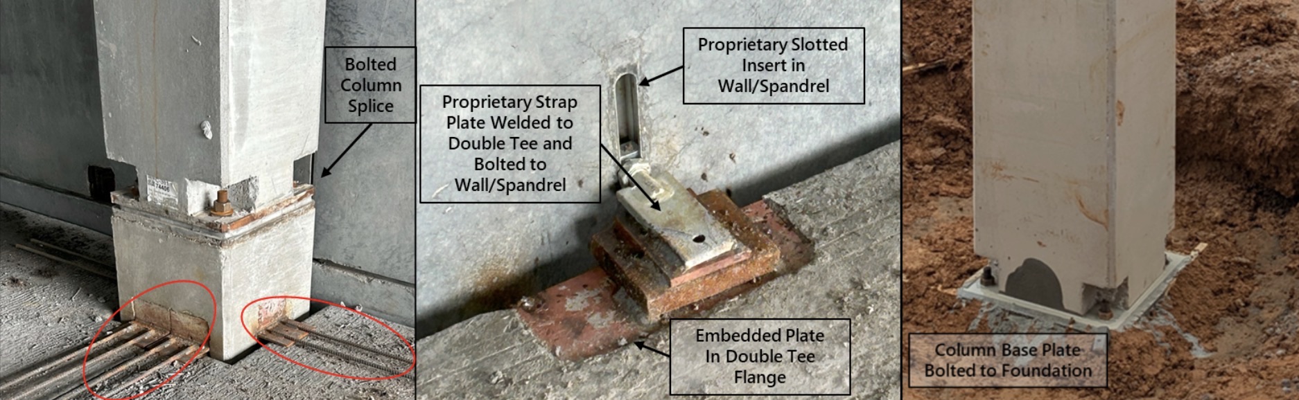
Bolted connections are used in a variety of ways, with the most common use being securing a precast column to a Cast-in-Place (CIP) footing (right side of Figure 3) and splicing two precast columns together (left side of Figure 3). Bolted connections in combination with welds are also used with a slotted proprietary insert and strap plate that allows unrestrained vertical movement between two precast members – see middle photo in Figure 3.
Wet Connections
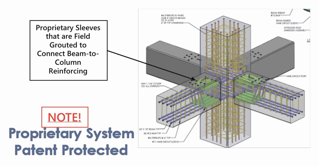
Wet connections are generally used for special applications. They incorporate grout and/or CIP concrete to tie various precast elements together. The red ovals in the left photo in Figure 3 indicate where reinforcing bars that are welded to a steel plate extend into an area that will receive CIP concrete topping over the double tee flanges. This CIP concrete will then tie the column to the floor system. This particular connection shows how sometimes dry and wet connections can be used together. Figure 4 shows a Tindall patented wet connection using field-grouted proprietary reinforcing bar coupling sleeves to create a rigid connection between beams and columns.
Proprietary Connection Parts and Systems
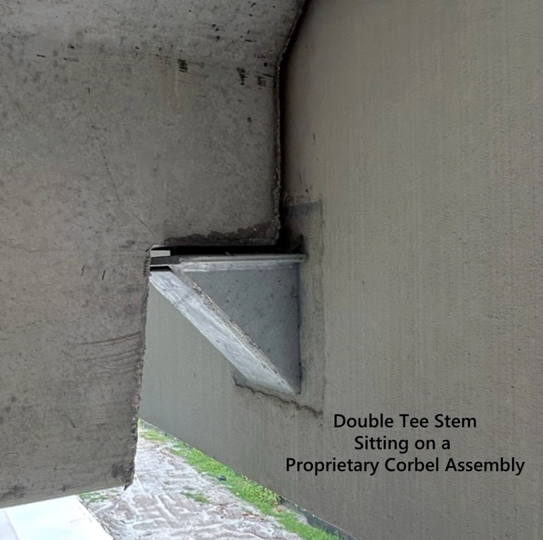
There are companies that direct a large portion of their business to the precast industry. They have come up with some creative and practical connection parts and systems. These include items such as slotted inserts that allow unrestrained differential movement between members, reinforcing splicing systems, corbels to support stair landings and double tees, and other similar connection concepts. Some of these have been shown in Figures 3 and 4. A double tee stem supported by a proprietary corbel is shown in Figure 5.
Summary
The connection systems used to tie various precast members to each other are critical to the stability, performance, and function of the overall structure. Proper concepts and designs of connections are an important aspect of a successful precast project.
Though precast connections can be complicated, Tindall has engineers on staff who can assist with load calculations and design the proper connections to support your structure. On a typical project, Tindall has an engineer who can serve as the “Specialty Structural Engineer (SSE)” or “Precast Engineer,” not to be confused with the Engineer of Record (EOR). Though they often work hand in hand, to complete the project design, the Precast Engineer is only responsible for the precast portion, generally from the top of the foundation up. In comparison, the EOR is accountable for the entire structure, foundation design, and applicable code requirements. Contact Tindall today to begin developing your next project.